Manholes, cabinets and poles are point objects that connect or terminate segments. Duct insertions, fittings, closures and terminators can be assigned to them. All properties of manholes, cabinets and poles can be described in various ways by attributes in the respective form.
Creating
To create manholes, cabinets and poles, you can proceed as described in Inserting new objects.
Manholes, cabinets and poles can be imported from plans (already as the respective object), or you can digitize them yourself or include them from imported point geometries (e.g., from the survey).
Import from a plan:
Digitize


Import from point geometry


If a closure or terminator is already located at the position, a query appears as to whether the manhole/cabinet/pole is to be assigned to that closure or terminator.
Modification
Various attributes can be assigned to manholes, cabinets and poles for a more detailed description. These attributes can be used for stylization in the display model and to modify the presentation in the graphic.

The geometries of manholes, cabinets and poles can be adjusted retrospectively by checking them out and moving them to a different position. Pay attention to the set and activated object snap. The objects should then be checked in again.
The question of a possible assignment also arises when moving a manhole/cabinet/pole to the position of a closure or terminator:
Assignments
Terminators and closures
In addition to the General and Table tabs, the form for manholes, cabinets and poles also has the Terminators/Closures tab:

FO/TP Terminators and FO/TP Closures can be assigned to manholes, cabinets and poles in this tab.


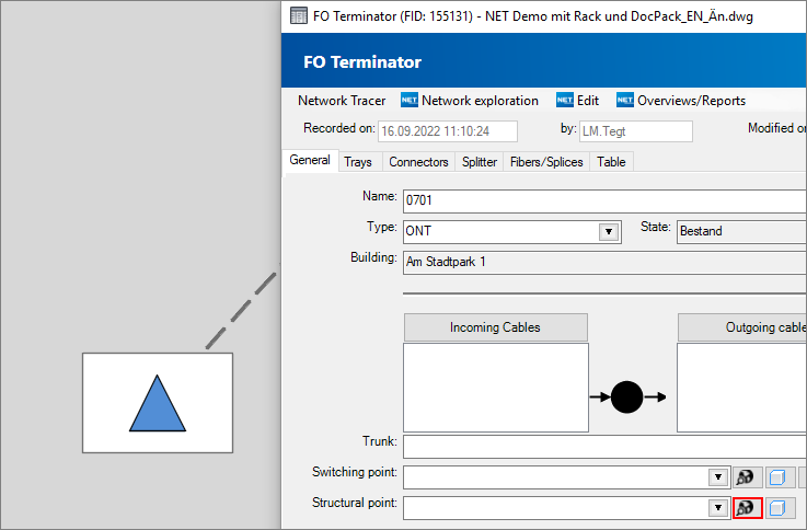
The terminator/closure is selected in the graphic.
The following information will appear:

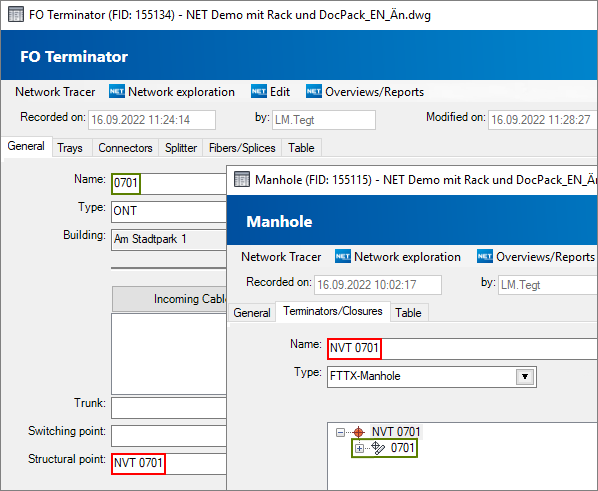
The tab shows which terminator/closure has been assigned to the manhole/cabinet/pole.

The assignment between the manhole/cabinet/pole and the terminator/closure can also be reversed. It is also possible to assign a structural system to the terminator/closure.

Then too, the assignment can be seen both in the terminator/closure and in the manhole/cabinet/pole.

Duct insertions and fittings
Fittings and duct insertions are assigned differently. When creating duct insertions, a prompt asking to which manhole/cabinet/pole or building the duct insertion is to be assigned already appears during the workflow. The assignment can then be seen both in the duct insertion and in the manhole/cabinet/pole or building.
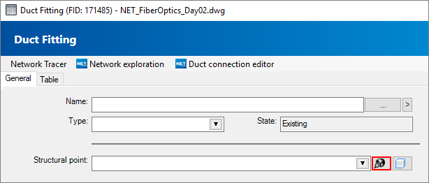
This is not the case for fittings, which must be subsequently assigned to the manhole/cabinet/pole. This can be done for individual fittings by selecting the respective object (manhole/cabinet/pole) in the graphic or from the list in the form for “installed in”:

If several fittings are to be assigned simultaneously, this is best done with “change globally” for the appropriately filtered fittings.
Deleting
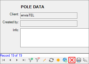
Manholes, cabinets and poles can be deleted in the tabs or via the form.
Tab: Segment, Home or NET
In the form
