Tabs
The “General” home tab contains general information, such as name and type. Incoming and outgoing splitter paths can be displayed under “Connections”.
| Attribute | Description |
| Name | The name of the splitter is displayed. This is automatically assigned during creation and is a combination of the splitter type and a consecutive number in brackets. The name can be changed here. (1) |
| Type | The splitter type is displayed. Double-clicking in the list box opens the form for the splitter type. New records can be created. (2) |
| Splitter paths | The number of splitter paths (INs and OUTs) is displayed. Clicking on  opens the detailed forms for all displayed splitter paths. (3) opens the detailed forms for all displayed splitter paths. (3) |
| Installt in | The feature class and the name of the higher-layer point (terminator or closure) to which the splitter is assigned are displayed. The  button highlights the higher-layer point in the graphic. The button highlights the higher-layer point in the graphic. The  button opens the form for the current terminator or the current closure. (4) button opens the form for the current terminator or the current closure. (4) |
| Tray | The splitter can be assigned to a tray. The page and the number of the tray are displayed. (5) |
| Connections | The forms for the incoming and outgoing splitter paths can be opened under Connections. (6) |
| Info | Information about the splitter can be entered. (7) |
| Details | If a specific attenuation has been specified for the splitter, the number of the corresponding records is displayed and the splitter data form can be opened. (8) |
| Documents | This displays whether documents have been attached to the form. (9) |
Menu items
A Connection Overview can be displayed via “Network exploration”.

The FO Connection Plan and the forms for the generated labels can be opened via the “Overviews/Reports” menu.

Splitter path
Tabs
The “General” home tab contains general information, such as name and type.

| Attribute | Description |
| Name | The name of the line to the splitter path is displayed. Clicking on the  button opens the line form for the current splitter path or, with button opens the line form for the current splitter path or, with  , all splitter paths in the filter. The number of the splitter path is displayed. (1) , all splitter paths in the filter. The number of the splitter path is displayed. (1) |
| Type | The type of the splitter path (IN/OUT) is displayed. (2) |
| Service | The service connected to the splitter path is displayed or can be selected from a drop-down list using |
| Tray | The name and number of the Tray in which the splitter was created is displayed. (4) |
| Splice place | The splice place occupied by the splice between the splitter path and the fiber is displayed. (5) |
| Connections | The name of the splitter to which the splitter path belongs is displayed. The  button opens the detailed form for the corresponding splitter. Clicking on button opens the detailed form for the corresponding splitter. Clicking on  highlights the point in the graphic in which the splitter belonging to the splitter path was created. (6) highlights the point in the graphic in which the splitter belonging to the splitter path was created. (6) |
| Connected objects | The objects connected to the splitter path (fibers / connectors / patch fibers / splitter paths) and the names of the associated points or lines are displayed. The  button opens the detailed form for the associated fiber, connector, patch fiber or splitter path, or of the cable section or terminator/closure. (7) button opens the detailed form for the associated fiber, connector, patch fiber or splitter path, or of the cable section or terminator/closure. (7) |
| Information | Information on the splitter path can be stored. (8) |
| Details | You can enter the length of the splitter path or enter it as the user length in the associated line form. (9) |
| Documents | This displays whether documents have been attached to the form. (10) |
Menu items
A Connection Overview can be displayed via “Network exploration”.

Services can be transferred to and removed from the selected network path or the network paths of the elements in the filter via the “Edit” menu.

A service can be transferred from the splice to the network path.
A service can be transferred from the splices in the filter to the corresponding network paths.
A service can be removed from the network path starting from the splice.
A service can be removed from the corresponding network paths starting from the splices in the filter.
The FO Connection Plan and the forms for the generated labels can be opened via the “Overviews/Reports” menu.

Splitter data
The detailed form for splitter data is opened under Details in the detailed form for splitters:
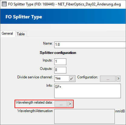
or in the Splitter Type under Wavelength related data:

Information for a splitter type, such as wavelength and attenuation, are managed in the “General” home tab.

1. Select the splitter to which the splitter data is to be applied.
2. Select the splitter type to which the splitter data is to be applied.
3. Select the wavelength. Double-clicking in the list box opens the form for the wavelength.
4. Input of the attenuation value.
5. This displays whether documents have been attached to the form.