Communication networks are described using the point-and-line model. Points are set at all branches. Lines meet at the points. The lines are topologically connected to one another via the points.
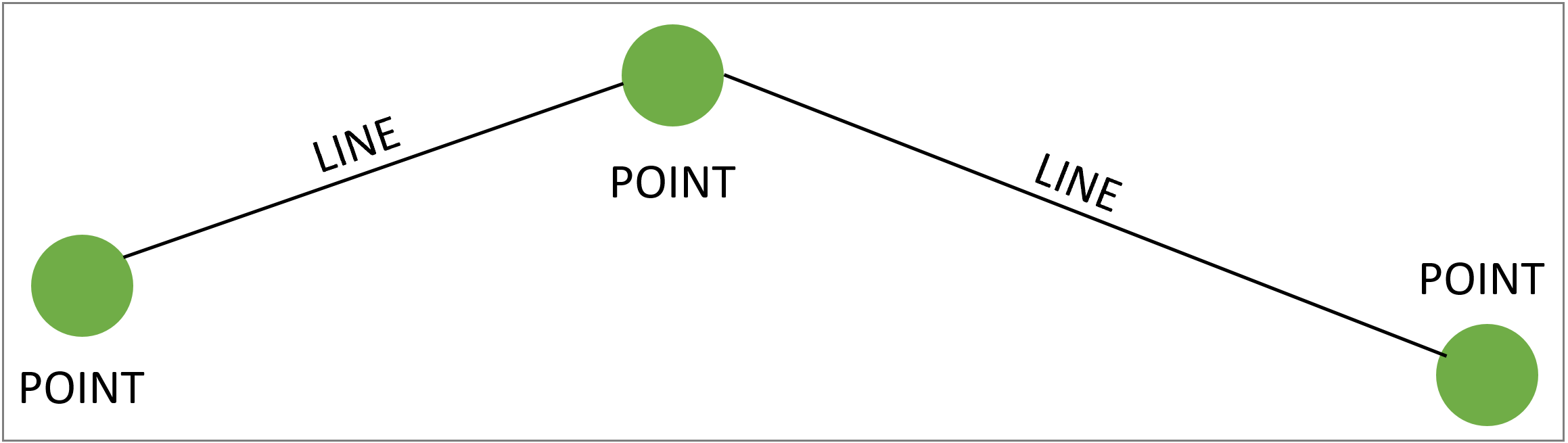
The points and lines forms therefore also play a key role in navigating the network.
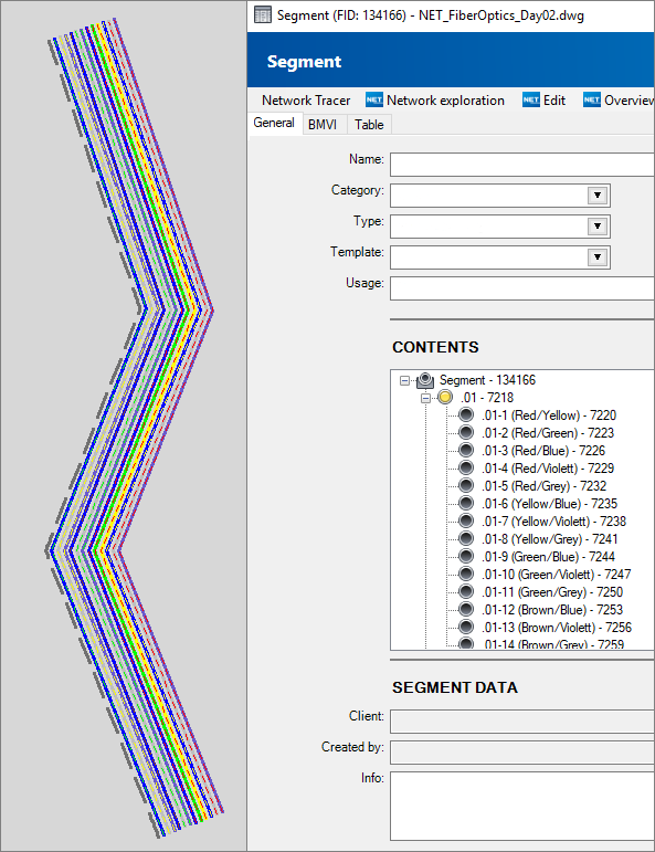
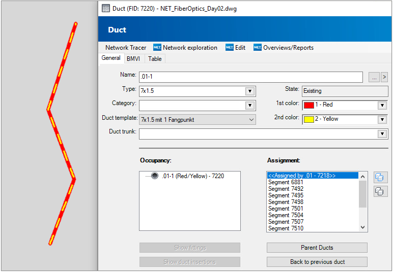
Transferred to a net, the lines represent the cables, ducts and segments. The lines can be drawn with their own geometries. This can then be seen in the graphic and can be selected there.
Points are the closures and terminators for cables, and the fittings and duct terminators for ducts.
Subordinate objects, such as fibers in the cable, connectors and splices in the terminator, microducts in the multi-duct bundle, are usually described without their own geometries.
If cables and ducts are to be described without their own geometries, an assignment is made using various workflows.
Example: Segment with geometry—assigned ducts without geometries
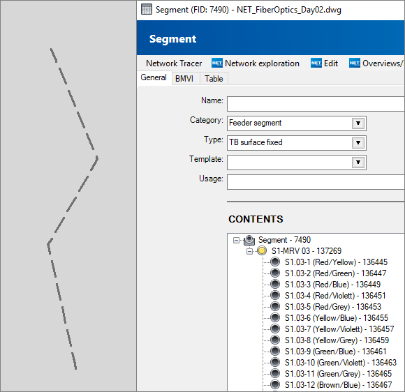
Example: Duct with geometry—assigned microducts without geometries
Example: Segment with geometry—assigned microduct composite without geometry, microducts with geometry