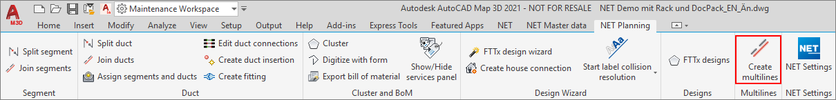
The workflow for creating multiple lines (for ducts and cable sections) is started in the “NET Planning” tab.
The following dialog opens:
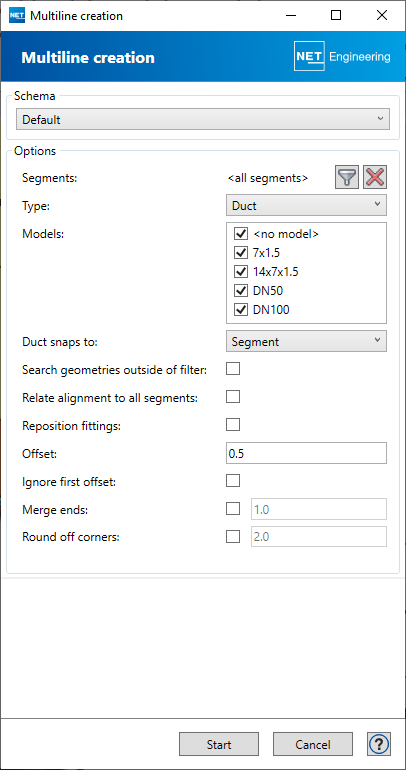
Options
| Segments | The cable or duct geometry can be created for cables or ducts of all or previously filtered segments. In this case, the geometries are also created for ducts that are connected to the selected ducts via fittings. |
| Type | It must be selected whether the geometry for ducts or cables is to be created. |
| Models | The geometry can be created for all defined or selected models. All models can be activated or deactivated with a click in the context menu. Individual models are activated by setting a checkmark. |
|
Duct snaps to: (only for type = Duct) |
The geometry to which the newly created duct geometry is to snap can be selected here. If you want the geometries of drop microducts to be drawn as far as the geometries of the composite ducts, you have to perform 2 steps. Step 1: Create geometries of the bundles with “… snaps to: segment”, then create the geometries of the drop microducts by “… snaps to: duct”. |
| Search geometries outside of filter | The geometries can also be created for ducts and cables that are assigned beyond the filtered segments. |
| Relate alignment to all segments | The optimization of duct/cable geometries can also be applied to the cross-filter segment geometry. |
|
Reposition fittings (only for type = Duct) |
When producing the duct geometry, the fittings are displaced to the corresponding point of the duct geometry. The implementation takes place only if the geometries for both connected ducts are created. |
| Offset | The distance of the duct/cable geometry from the reference trench can be specified. This is stated in meters [m]. If the language setting is English, a period (.) is used as the decimal separator; if the language setting is German, a comma (,) is used. With a negative offset, the geometries are created on the other side of the trench. |
| Ignore first offset | If this option is selected, the first duct/cable geometry is placed directly on the trench geometry. This is recommended if the trench geometry is to be hidden for displays of the duct/cable geometry. |
| Merge ends | Disabled Enabled |
| Round off corners | Enabled |
Click the Start button to start creating the geometry for cables or ducts.
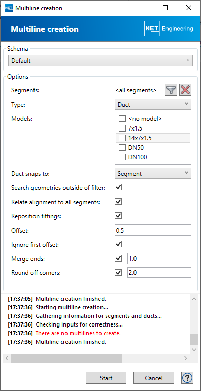
The information field announces the successful execution of the workflow or displays errors in the creation.
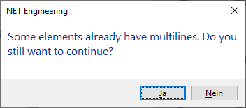
Restarting the workflow overwrites existing geometries after a notification message if YES is selected.
To delete duct and cable geometry, please use the workflows from the segment form.
Note
The ducts and cables must be stylized accordingly in the display model.