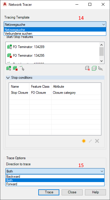
In each form, the user will find the command “Network Tracer” in the upper left part. Tracing as well as routing can be carried out. In routing, a NETwork path finding is carried out from a start point to an end point. A tracing searches for all connected elements. The direction of the search can be defined by the user. Likewise, intermediate points that the searched network path is to avoid or use can be defined.
Network Tracer using the example of a point
The Network Tracer command opens a selection for specifying the current object. The user can set the current element as a start, stop or end object for network tracer.

The Network Tracer form is opened after a selection has been made.
Explanation of the Network Tracer form

1. This displays the object selected for network tracing (with FID). The preceding symbol indicates whether the selected element was selected as a start, stop or end object.
2. Symbol for a start object. A new start object can be selected from the graphic by clicking on the button.
3. Symbol for a stop object. A new stop object can be selected from the graphic by clicking on the button.
4. Symbol for an end object. A new end object can be selected from the graphic by clicking on the button. This is possible only with the “Netzwegsuche”, but not with “Verbundene suchen”.
If “Verbundene suchen” has been selected as the network tracer template, the network tracer can be started after selection of the start and possibly a stop object, as well as the direction of the network tracing.
The results are listed, can be highlighted in the graphic or opened in the form.

If “Netzwegsuche” has been selected as the network tracer template, an end object can be selected in addition to the start and stop objects.

5. The elements selected via buttons 2–4 are displayed in form field 5.
6. Selected elements for network tracer can be removed using this button.
7. Selected elements are highlighted in the graphic.
8. Selected elements are highlighted with zoom in the graphic.
In the Stop conditions subform, user-defined conditions for network tracer are displayed.

9. New stop conditions can be defined via this button.
10. Stop conditions can be edited.
11. Stop conditions can be deleted.

12. For creating new stop conditions via button 9, the editor 12 opens. An existing stop condition can be selected from the list or a new condition can be defined by clicking on the button. Feature classes, attributes and domain values can be selected.
If the stop conditions have been defined and confirmed with OK, they appear in the corresponding window.

13. This displays the defined stop conditions in the form.

14. Selecting the network tracer types
NETwork path finding: Executes a routing from start point to end point.
Find connected: Executes a tracing across all connected elements.
15. Selecting the network tracer direction
Both: Performs network tracer in both directions.
Forward/Reverse: Performs network tracer in the selected direction.
16. Controls the inclusion of stop objects in the network tracer.

17. The “Trace” button starts the network tracer with the selected options.
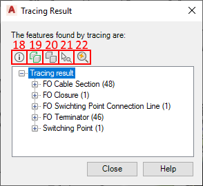
The result of the network tracer is displayed in the Tracing Result form.

18. The forms for the result elements are opened.
19. The network tracer result is displayed in the graphic.
20. The highlight is canceled.
21. Selected elements are zoomed in on.
22. The zoom is done by clicking. If this function is activated, the selected object is zoomed in on.