Exporting to SDF
The DXF or DWG file to be converted into an SDF file must be prepared accordingly before conversion. For this purpose, the drawing units must be adapted, the layer structure must be prepared and the drawing needs to be cleaned up. The cleaning is done either with the “Mapclean” command or with the “Clean” command.
Drawing units
The drawing units in the DWG file that is to be used to create the SDF file should match the units of the project. By entering the UNITS (or EINHEIT) command, the following dialog box appears:

Make sure that the unit for the insertion scale from the DXF matches the insertion scale in the project.
Layer structure in the DWG file
The DWG file should be well structured with regard to layers.
- The representation of the most varied elements in the same layer (e.g., usage types, street names and buildings in layer 0815) is not ideal.
- The content should be recognizable from the layer names.
- Line-accompanying symbols should be located on the appropriate layer. The display of various symbols on layer “0” is not ideal.
- Tried-and-tested layer structures should preferably be adopted.
- For data from the real-estate cadaster, the layers (slides) of the property key catalogs of the real-estate cadasters of the respective federal states are recommended (OSKA-LIKA).
- Good structuring means that, later, it will be easier to display and hide individual data by topic.
Cleaning the drawing with MAPCLEAN
The “Mapclean” command (Planning and Analysis workspace, Extras group) checks the elements of the drawing.
1. Selection of the elements to be processed—preferably all of them.

2. Cleaning operations: duplicate objects and objects with zero length are deleted.

3. Selection of the Cleanup Method

4. Finish
5. The cleaning process should be carried out once again with the item “Dissolve Pseudo Nodes” selected in step 2. Thus, for example, building perimeters that previously consisted of individual lines are converted into polygons. These can then be given area fills in the project.

The number of objects cleaned is displayed.

Cleaning the drawing with CLEAN
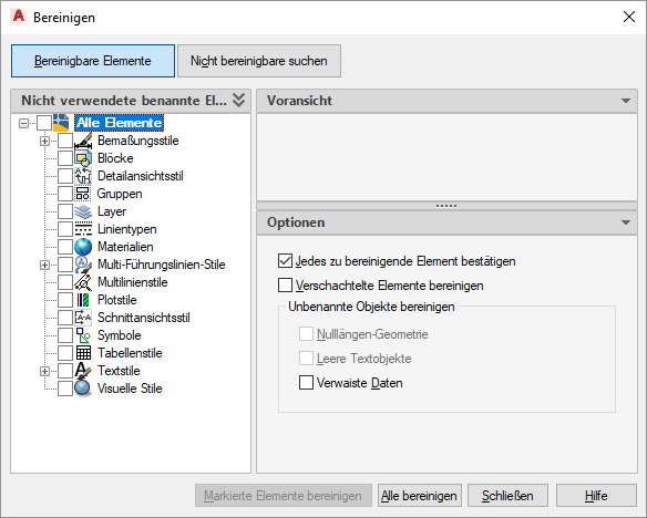
The Clean command displays all the elements of a drawing that can be cleaned.

Unused elements, such as dimensioning styles, layers and text styles, are removed from the drawing.
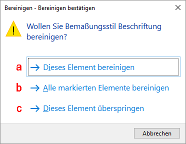
The objects can (a) be cleaned individually, (b) all objects can be cleaned in one step, (c) individual objects can be excluded from the cleanup.

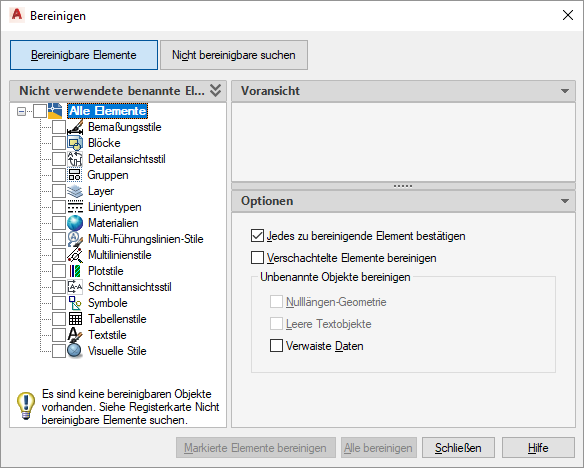
The cleanup may need to be performed several times. Only when no elements to be cleaned are displayed is the drawing error-free.

Creating the SDF file
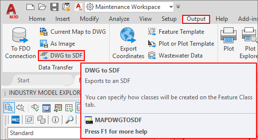
Use the MAPDWGTOSDF command or the Output tab in the Data-transfer group to start the process.

1. The directory and file name of the SDF file to be created must be specified.

Note
If the SDF file already exists, the data for the existing file can be added or the existing file can be overwritten. Please note that data already present in the SDF file should not be added again (duplicate data).
2. In the “Selection” tab, the objects to be exported are selected

Normally, the option “Select all” is selected under “Select objects to export”, since the DWG file has already been prepared in advance.
You can also use the “Select manually” option and/or the “Filter selection”, where, for example, the corresponding layers to be exported can be selected. (“ * ” stands for “all layers”).
3. If a saved profile is already available, it can be accessed by clicking on the “Load” button,

;the entries stored in the corresponding EPF file open:

The settings previously made in the dialog box are overwritten by the settings of the EPF file.
Further settings can be made and the modified profile can be saved again.
4. The “Feature Class” tab defines how the individual feature classes should be created.

If you select the option “Create multiple classes based on a drawing object”, the individual classes/layers can also be shown and hidden later in the project.
5. For the correct display of the objects in the display model, attributes of the individual objects must also be transferred into the SDF file.
The selection of attributes depends on the objects to be exported and the information required in the project in the SDF data.
For example, in the properties, the values for

- Angle
- Color
- Layer
- Radius
- String
- Type
are specified.
In the object properties for blocks, among other things,

- Class Name
- Color
- Layer
- Linetype
- Linetype scale
- Lineweight
should be specified.
For texts, the information on

- Contents
- Height
- Rotation
are important to permit an appropriate display.
Depending on the data, further attributes may be necessary for a display.
6. In the Options tab, in the Miscellaneous section, the “Treat closed polylines like polylines” check box should be selected.

For example, it is possible to create surfaces from closed polylines for buildings and other objects.
After all the corresponding settings have been made, the profile should be saved in order to be able to use the settings again at a later time.


Clicking on “OK” starts the export of the data and saves it in the SDF file.
Note
The SDF must be created with the string and rotation properties for transferring the orientation of texts. In the display model, for example, the rotation can then be adopted for texts. Depending on the angle units in the source and target file, a conversion between degree and gons must be carried out.