Warnings and Error messages during the calculation
Warning of not connected points
“Nodes are not connected to the rest of the area”
The calculation of the system has two stages. In the first step of the calculation, the potential trench network is converted into a point and line model. All trenches are broken at crossings and at these points additional points are created. After this process, the following statement appears:
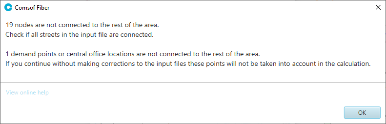
- “19 nodes are not connected:” > The 19 nodes listed in the example are not connected to the rest of the trench network. This is due to unconnected street center lines.
- “1 demand points or central office locations are not connected:” > Sometimes, one of the 19 nodes might be a demand point. This means that the demand point is not connected to the remaining potential trench network.
Solution:
Evaluate the affected points and check the trench network.
Multiple connections are not supported
“Multiple connections are not supported”
During the calculation, the calculation process may be aborted if clusters overlap and demand points are located in this overlap region.
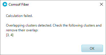
Demand points must lie unambiguously in one cluster.
Solution:
Prior to the calculation, perform an project validation. There, these points are displayed and you have the option of manually correcting the course of the clusters.
Errors in Design Rules
Errors that occur within the planning settings are listed in a dialog box and must be corrected.
Error message
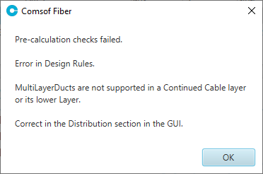
MultiLayerDucts are not supported in a Continued Cable Layer or its lower Layer
Interpretation
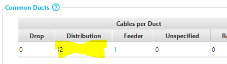
General ducts are not supported in connection with the distribution network strategy "Direct cable to the building (no additional house connection cable)".
Solution
Change the settings for General ducts and remove the use of defined ducts for the distribution layer.
Error Message
No ducts found. Add at least one undergrund duct.
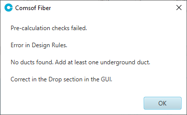
Interpretation
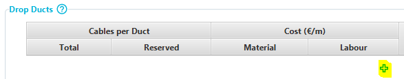
No duct type has been defined in the drop section.
Solution
Define a usable duct in the drop section. Use the "plus".
Planning settings do not exist
“No Rules & Material file was selected”
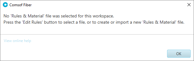
Solution:
In this case, creating the planning setting has been forgotten and needs to be created.
Warnings after the calculation
In contrast to the error messages, warnings at the end of the calculation are merely notes on the calculation. The calculation itself has been successfully completed.
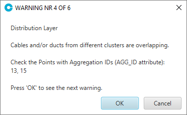
Cables and/or ducts of different clusters are overlapping (Distribution Layer)
“Cables and/or ducts from different clusters are overlapping”
This warning message indicates that cables and/or ducts of different clusters are laid in the same trenches. In other words, cables and/or ducts of one cluster are partially laid in another cluster.
The specified AGG_ID designates the cluster from which cables run in other clusters.
Solution:
The easiest way to find the locations is to only show the layer of the distribution cables. In this way, you can recognize the affected area. The clusters must then be corrected there accordingly.
Clusters greater than the specified cluster size of 86 have been found
“Clusters are very small compared to maximum size”
If clusters are blocked or clustered automatically due to the distance determination (see Rules Distribution Layer), there may be a notice after the calculation that clusters are too small.
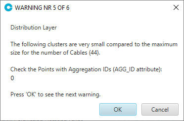
In the example, the cluster with AGG_ID 0 is too small. According to the planning settings, a maximum of 48 cables should be connected in a cluster. In the “0” cluster, however, only 2 cables are connected.
The same can also happen if clusters are larger than the set cluster size from the planning settings.
Solution:
Adjustment of the cluster size with blocked input clusters.
Blocked point is ignored
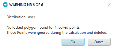
“No locked polygon found”
Specified points are ignored by the system in the calculation if the associated cluster was not locked. This warning can arise at all network layers. Here is the example of an ignored distribution point in the distribution layer.
Solution:
Lock the cluster associated with the network point.
Maximum blowing-in length exceeded
“Exceeds cut-off distance”
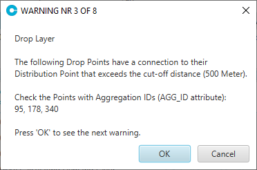
If too short blowing length is selected or the demand points are too far apart, it may be that the double blowing length is exceeded when setting an additional handhole. This warning can arise at all network layers. Here is the example for the distribution layer.
Error message for manual rings
BackBone Layer: Edges in Connection Layer and Cable Layer do not match
Solution