On the Components tab,
- the trench types and their costs and the way of creating the trenches
- the duct types, their costs and the way in which they are used
- the cable types, their costs and the way in which they are used
- the distribution closure types, their costs and their capacities in terms of outgoing ducts and numbers of fibers
- the splice closure types and their suitability for use in the network layers
are defined.
Street and Trench types
Trench types can be created via an import (menu item “Edit”). Values can also be generated manually. The costs for parallel laying or crossing must be added manually.

The type of trench creation— both / single sided is used when setting trench-network type = sidewalk network (General tab).
The classification can take the values “Street”, “Bridge” and “Tunnel”. 
Duct types
Duct types are created manually and allocated a price.
In multi-duct bundles, the sum of the “Inner ducts” and “Spare ducts” corresponds to the total number of microducts.

The layers in which ducts can be used are set under drop layer, distribution layer, feeder layer and backbone layer.

Installation type
The installation type defines how the duct may be used.
- Buried > Duct is planned in the trench
- Pull in > Duct can be drawn into an existing duct
- Existing > Identification of an existing duct
Embedding
The embedding defines whether ducts or cables may be planned in the duct.
- Blow in > Cable can be blown into the duct
- Pull in > Another duct can be drawn into the duct

Outer diameter / Inner diameter
Outer and Inner diameters control the usability of ducts.
Cable types
Records are kept of the price, number of fibers per bundle and the Amount bundles as well as Spare bundles for the cable types. The sum of the Amount bundles + Spare bundles equals the total number of bundles.

The layers in which cables can be used are set under drop layer, distribution layer, feeder layer and backbone layer.
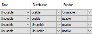
The installation type defines how the cable may be used. The outer diameter controls the use of cables in ducts.

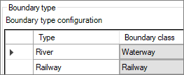
Boundary type
The boundary types defined in the project are displayed here and can be assigned to a boundary class.
Note: atesio takes boundary into account only when creating the drop trenches. If a record is set to “May be crossed” = “NO”, the preprocessing will look for an alternative drop trench if possible.
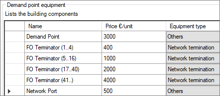
Demand point equipment
This is were you can define which components can be planned at the demand point.
- Name and price are entered manually.
- The type of equipment is assigned via a drop-down menu.
The components defined here are used in the Configuration tab under Demand point equipment configuration.
Cfd equipment
Cfd points are layer points at the distribution layer. They are used to bring fibers to a specific location, such as mobile phone locations or layer points for future construction or commercial areas.
- Name and price are entered manually.
- The type of equipment and the structure type are assigned via a drop-down menu.
The components defined here are used in the Configuration tab under Cfd equipment configuration.

Backbone demand equipment
Backbone demand are layer points at the feeder-cable layer.
- Name and price are entered manually.
- The type of equipment and the structure type are assigned via a drop-down menu.
The components defined here are used in the Configuration tab under Backbone demand equipment configuration.

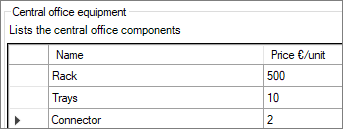
Central office equipment
This is where the components with which a Central office can be equipped are defined.
The components defined here are used in the Configuration tab under Central office equipment configuration.
Note: The setup costs for the Central office are stored directly in the record for the “default” layer point at feeder cable layer.
Central-Office line card types

Central-Office switch types

Central-office ODF types

Distribution closure types
Under this topic, the layer point is configured at the distribution layer.
- Name and price are entered manually.
- The capacities of distribution closures are defined by the number of outgoing ducts and fibers.
- By selecting the corresponding structure type, it is defined whether a manhole or cabinet is set at the distribution point. The selection is made from a drop-down menu.

Fiber splice closure types
This topic is used to define the Fiber splice closure types that can be used throughout the project.
- Name, price and number of fibers are entered manually.
- The control of the use of splice closures is defined via the corresponding attribute entries in the layers—distribution layer / feeder layer / backbone layer.
- The structure type is selected from a drop-down menu.

Splitter types
This is where splitters are defined with a splitting ratio and price.

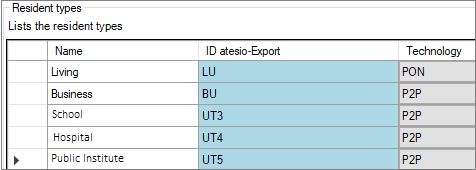
Resident types
The types of demand units are defined under Resident types.
- The atesio export ID is the abbreviation that is used to calculate the fiber configuration in the Configuration tab under Demand-point equipment configuration and Demand-point fiber configuration.
- The technology with which the corresponding demand units are to be connected is defined under Technology.
